- Announcements
- BBQ and Food
- Cars
- Computing
- Cool Stuff
- Current Events
- Electric Vehicles
- Electronics
- Energy
- Flashahaulism
- Funny
- Government
- Hints and Tips
- History
- HVAC
- Induction heating
- Internet
- Lighting
- Misc
- Neon and other lighting
- Nuclear
- Personal
- Pets
- Philosophy
- Photography
- Power Generation
- Product Reviews
- Projects
- Q and A
- RV/Camping
- Science
- Tellico
Categories
Blogroll
 Print This Post
Using the Induction Heater – Neon Processing
PermaLinkMaking neon signs and artwork is what got me started on the induction heater quest in the first place. So now we’ve come full circle. Most people won’t have any need to process neon signs, of course, but I post this installment just for the fun of it and to show some eye candy.
In making a neon sign unit, first the glass tubing is heated and bent to the desired shape. Then neon electrodes are attached. Finally the tube is processed to remove impurities and air and then to fill the tube with the noble gas (neon or argon) to make it glow. Part of the processing is the heating of the neon electrode to convert the electron emissive coating on the interior of the electrode to its active form.
Traditionally this has been done by passing a high voltage high current through the tube while partially evacuated. This heats the glass and the electrodes – a desirable occurrence. But the rate of glass heating and the rate of electrode heating is often different and that is not desired. Induction heating is the Better Way. That separates the glass heating from the electrode heating.
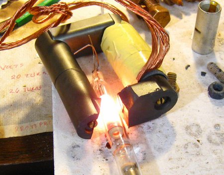
Here is a photo of an electrode being heated in the gap of the flux concentrator.
The induction heater is set to low power – about 400 watts. This is to avoid melting the trode and to make this video more interesting. Full power heats the electrode in a flash.
Posted by neonjohn on November 13th, 2010 under Cool Stuff, Induction heating
January 8th, 2012 at 2:34 am
On The page,making a circuit board,is a photo for a board. Is yhat board aviable of not .Is there pc board leout aviable so that a can make myn own pc board.
Thanks Arend
January 8th, 2012 at 2:44 am
Arend:
The circuit board artwork for my various heaters are available here:
http://www.neon-john.com/Induction/Index.htm
http://www.fluxeon.com also sells selected boards and board kits.
John
February 20th, 2012 at 5:19 pm
Hi John, since you use this Royer RF generator for neon electrode processing, the thought’s occurred to me that it could be used in a related capacity to drive a large high-frequency step-UP transformer for the purpose of tube bombarding, or for the purpose of operating major “plasma globe” type devices. I’m curious what your thoughts are about such usage–and if you know of anyone trying something like this with the Fluxeon products. Thanks!
February 20th, 2012 at 6:13 pm
Hey Carl,
In our Neon Roy unit I actually do step the RF voltage up to about 1500 volts so that the cable between the generator and work head can be smaller and more flexible.
I once hooked up an approx 2 ft long piece of 1″ cold cathode tubing to the generator. The results were spectacular. The tube was almost too bright to look at an the trodes got a dull red.
We’ve talked about trying high frequency for bombarding but just haven’t gotten the time. It would probably work, though 60hz bombarding would probably be cheaper.
It doesn’t require much current to heat the glass sufficiently once the trodes are to be processed separately. I know one guy who’s using a pair of 120 ma 12kV cold cathode transformers in parallel to supply the glass heating current. Since the transformers are constant current devices, no controls (other than a switch, of course) are necessary. Connect any length of tubing to the transformers and go.
I’m sure that one with the correct secondary would drive a single electrode display like a plasma globe quite well. The only problem that I could envision is there being so much RF present that everything metal you touch gives you little RF burns. Still, I’m going to try it one day.
John